![Thợ Sửa Máy Giặt [ Tìm Thợ Sửa Máy Giặt Ở Đây ]](https://thomaygiat.com/wp-content/uploads/sua-may-giat-lg-tai-nha-1.jpg)
DAIKIN R32 Split Series Room Air Conditioner Instruction Manual – Manuals+
DAIKIN R32 Split Series Room Air Conditioner Instruction Manual
Mục Chính
Safety Considerations
Refer also to the General Safety Considerations in the separate booklet.
DANGER
- Refrigerant gas is heavier than air and replaces oxygen. A massive leak can lead to oxygen depletion, especially in basements, and an asphyxiation hazard could occur leading to serious injury or death.
- Do not ground units to water pipes, gas pipes, telephone wires, or lightning rods as incomplete grounding can cause a severe shock hazard resulting in severe injury or death. Additionally, grounding to gas pipes could cause a gas leak and potential explosion causing severe injury or death.
- If refrigerant gas leaks during installation, ventilate the area immediately. Refrigerant gas may produce toxic gas if it comes into contact with fire. Exposure to this gas could cause severe injury or death.
- After completing the installation work, check that the refrigerant gas does not leak throughout the system.
- Do not install unit in an area where flammable materials are present due to risk of explosions that can cause serious injury or death.
- Safely dispose all packing and transportation materials in accordance with federal/state/local laws or ordinances. Packing materials such as nails and other metal or wood parts, including plastic packing materials used for transportation may cause injuries or death by suffocation.
WARNING
- Only qualified personnel licensed or certified in their jurisdiction must carry out the installation work. Installation must be done in accordance with this installation manual. Improper installation may result in water leakage, electric shock, or fire.
- Pipe work and installation shall be in compliance with national codes (ASHRAE15 or IRC).
- When installing the unit in a small room, take measures to keep the refrigerant concentration from exceeding allowable safety limits. Excessive refrigerant leaks, in the event of an accident in a closed ambient space, can lead to oxygen deficiency.
- Use only specified accessories and parts for installation work. Failure to use specified parts may result in water leakage, electric shock, fire, or the unit falling.
- Install the air conditioner or heat pump on a foundation strong enough that it can withstand the weight of the unit. A foundation of insufficient strength may result in the unit falling and causing injuries.
- Take into account strong winds, typhoons, or earthquakes when installing. Improper installation may result in the unit falling and causing accidents.
- Make sure that a separate power supply circuit is provided for this unit and that all electrical work is carried out by qualified personnel licensed or certified in their jurisdiction according to local, state, and national regulations. An insufficient power supply capacity or improper electrical construction may lead to electric shock or fire.
- Make sure that all wiring is secured, that specified wires are used, and that no external forces act on the terminal connections or wires. Improper connections or installation may result in fire.
- When wiring, position the wires so that the electrical wiring box cover can be securely fastened. Improper positioning of the electrical wiring box cover may result in electric shock, fire, or the terminals overheating.
- Before touching electrical parts, turn off the unit.
- The circuit must be protected with safety devices in accordance with local and national codes, i.e. a circuit breaker.
- Securely fasten the outdoor unit terminal cover (panel). If the terminal cover/panel is not installed properly, dust or water may enter the outdoor unit causing fire or electric shock.
- When installing or relocating the system, keep the refrigerant circuit free from substances other than the specified refrigerant (R32) such as air. Any presence of air or other foreign substance in the refrigerant circuit can cause an abnormal pressure rise or rupture, resulting in injury.
- Do not change the setting of the protection devices. If the pressure switch, thermal switch, or other protection device is shorted and operated forcibly, or parts other than those specified by Daikin are used, fire or explosion may occur.
- When installing or relocating the air conditioner, do not let any other substances besides R32, such as air, enter the refrigerant circuit. The presence of air or foreign matter in the refrigerant circuit causes an abnormal pressure rise, which may result in equipment damage and even injury.
- Do not use means to accelerate the defrosting process (if possible) or to clean, other than those recommended by the manufacturer.
- The appliance must be stored in a room without continuously operating ignition sources (for example: open flames, an operating gas appliance or an operating electric heater).
- Do not pierce or burn.
- Be aware that refrigerants may not contain an odor.
- Comply with national gas regulations.
CAUTION
- Do not touch the switch with wet fingers. Touching a switch with wet fingers can cause electric shock.
- Do not allow children to play on or around the unit to prevent injury.
- Wear adequate personal protective equipment (protective gloves, safety glasses,…) when installing, maintaining or servicing the system.
- The heat exchanger fins are sharp enough to cut. To avoid injury, wear gloves or cover the fins while working around them.
- Do not touch the refrigerant pipes during and immediately after operation as the refrigerant pipes may be hot or cold, depending on the condition of the refrigerant flowing through the refrigerant piping, compressor, and other refrigerant cycle parts. Your hands may suffer burns or frostbite if you touch the refrigerant pipes. To avoid injury, give the pipes time to return to normal temperature or, if you must touch them, be sure to wear proper gloves.
- Install drain piping to ensure proper drainage. Improper drain piping may result in water leakage and property damage.
- Insulate piping to prevent condensation.
- Be careful when transporting the product.
- Do not turn off the power immediately after stopping operation. Always wait for at least 5 minutes before turning off the power. Otherwise, water leakage may occur.
- Do not use a charging cylinder. Using a charging cylinder may cause the refrigerant to deteriorate.
- Refrigerant R32 in the system must be kept clean, dry, and tight.
(a) Clean and Dry — Foreign materials (including mineral oils such as SUNISO oil or moisture) should be prevented from getting into the system.
(b) Tight — R32 does not contain any chlorine, does not destroy the ozone layer, and does not reduce the earth’s protection again harmful ultraviolet radiation. R32 can contribute to the greenhouse effect if it is released. Therefore take proper measures to check for the tightness of the refrigerant piping installation. Read the chapter Refrigerant Piping Work and follow the procedures. - The indoor unit is for R32. See the catalog for outdoor models that can be connected. Normal operation is not possible when connected to non-compatible outdoor units.
- Remote controller (wireless kit) transmitting distance can be shorter than expected in rooms with electronic fluorescent lamps (inverter or rapid start types). Install the indoor unit far away from fluorescent lamps as much as possible.
- Do not install the air conditioner or heat pump in the following locations:
(a) Where a mineral oil mist or oil spray or vapor is produced, for example, in a kitchen. Plastic parts may deteriorate and fall off or result in water leakage.
(b) Where corrosive gas, such as sulphurous acid gas, is produced. Corroding copper pipes or soldered parts may result in refrigerant leakage.
(c) Near machinery emitting electromagnetic waves. Electromagnetic waves may disturb the operation of the control system and cause the unit to malfunction.
(d) Where flammable gas may leak, where there is carbon fiber, or ignitable dust suspension in the air, or where volatile flammables such as thinner or gasoline are handled. Operating the unit in such conditions can cause a fire. - Take adequate measures to prevent the outdoor unit from being used as a shelter by small animals. Small animals making contact with electrical parts can cause malfunctions, smoke, or fire. Instruct the user to keep the area around the unit clean.
- Servicing shall be performed only as recommended by the manufacturer and licensed or certified in their jurisdiction.
NOTE
- The indoor unit should be positioned where the unit and interunit wires (outdoor to indoor) are at least 3.3ft (1m) away from any televisions or radios. (The unit may cause interference with the picture or sound.) Depending on the radio waves, a distance of 3.3ft (1m) may not be sufficient to eliminate the noise.
- Dismantling the unit, treatment of the refrigerant, oil and additional parts must be done in accordance with the relevant local, state, and national regulations.
- Only use tools for R32 or R410A, such as a gauge manifold, charge hose, gas leak detector, reverse flow check valve, refrigerant charge base, vacuum gauge, or refrigerant recovery equipment.
- If the conventional refrigerant and refrigerator oil are mixed in R32, the refrigerant may deteriorate.
- As maximum allowable pressure is 604psi (4.17MPa), the wall thickness of field-installed pipes should be selected in accordance with the relevant local, state, and national regulations.
Accessories
Choosing an Installation Site
- Before choosing the installation site, obtain user approval.
1. Indoor unit
- The indoor unit should be positioned in a place where:
- the restrictions on the installation requirements specified in “Indoor Unit Installation Diagram” on page 4 are met,
- both the air inlet and air outlet are unobstructed,
- the unit is not exposed to direct sunlight,
- Install so that drainage occurs easily,
- the unit is away from sources of heat or steam,
- there is no source of machine oil vapor (this may shorten the indoor unit service life),
- cool/warm air is circulated throughout the room,
- the unit is away from electronic ignition type fluorescent lamps (inverter or rapid start type) as they may affect the remote controller range,
- no laundry equipment is nearby.
2. Wireless remote controller
- Turn on all the fluorescent lamps in the room, if any, and find a location where the remote controller signals are properly received by the indoor unit (within 23ft (7m)).
Indoor Unit Installation Diagram
CAUTION
- Do not hit or violently push the INTELLIGENT EYE sensor. This can lead to damage and malfunction.
- Do not place large objects near the INTELLIGENT EYE sensor. Also keep heating units or humidifiers outside the sensor’s
detection area.
Indoor Unit Installation
1. Installing the mounting plate
The mounting plate should be installed on a wall which can support the weight of the indoor unit.
1)Temporarily secure the mounting plate to the wall, make sure that the plate is completely level, and mark the drilling points on the wall.
2)Secure the mounting plate to the wall with screws.
Recommended mounting plate retention spots and dimensions
* Depending on the Model, the actual distance between the liquid pipe end and gas pipe end may differ from the distance between those symbols on the mounting plate ( the distance listed in this manual ). Always measure the actual distance between the liquid pipe end and gas pipe end before installing refrigerant pipes .
2. Drilling a wall hole and installing wall embedded pipe
WARNING
For metal frame or metal board walls, be sure to use a wall embedded pipe and wall hole cover in the feed-through hole to prevent possible heat, electric shock, or fire.
- Be sure to caulk the gaps around the pipes with caulking material. (to prevent condensation caused by intrusion of air from outside or within the wall) 1) Drill a feed-through hole with a 2-9/16 inch (65mm) (for 09/12 class), 3-1/8 inch (80mm) (for 18/24 class) diameter through the wall at a downward angle toward the outside. (to prevent water leakage) 2) Insert a wall embedded pipe into the hole. 3) Insert a wall hole cover into wall pipe. 4) After completing refrigerant piping, wiring, and drain piping, caulk the pipe hole gap with putty.
3. Installing the indoor unit
CAUTION
When unpacking and installing the product, do not strongly press the flaps. (The flap shafts may become deformed.)
In the case of bending or curing refrigerant pipes, keep the following precautions in mind. Abnormal sound may be generated if improper work is conducted .
- Do not strongly press the refrigerant pipes onto the bottom frame.
- Do not strongly press the refrigerant pipes on the front grille, either.
3-1. Right-side, right-back, or right-bottom piping
- Attach the drain hose to the underside of the refrigerant pipes with adhesive vinyl tape.
- Wrap the refrigerant pipes and drain hose together with an K insulation tape.
- Pass the drain hose and refrigerant pipes through the wall hole, then position the indoor unit on the mounting plate hooks, using the markings at the top of the indoor unit as a guide.
- Open the front panel, then open the service lid. (Refer to “Service lid” on page 4.)
- Pass the inter-unit wire from the outdoor unit through the feed-through wall hole and then through the back of the indoor unit. Pull them through the front side. Bend the ends of cable tie wires upward for easier work in advance. (If the interunit wire ends are to be stripped first, bundle wire ends with adhesive tape.)
- Press the bottom frame of the indoor unit with both hands until it is firmly caught by the A mounting plate hooks. Make sure that the wires do not catch on the edge of the indoor unit.
3-2. Left-side, left-back, or left-bottom piping
- Switch around the drain plug and drain hose.
- Attach the drain hose to the underside of the refrigerant pipes with adhesive vinyl tape.
- Shape the refrigerant pipes along the pipe path marking on the mounting plate.
- Pass the drain hose and refrigerant pipes through the wall hole, then position the indoor unit on the mounting plate hooks, using the markings at the top of the indoor unit as a guide.
- Open the front panel, then open the service lid. (Refer to “Service lid” on page 4.)
- Pass the inter-unit wire from the outdoor unit through the feed-through wall hole and then through the back of the indoor unit. Pull them through the front side. Bend the ends of tie wires upward for easier work in advance. (If the inter-unit wire ends are to be stripped first, bundle wire ends with adhesive tape.)
- Connect the refrigerant pipes.
- In case of pulling the drain hose through the back of the indoor unit, wrap the refrigerant pipes and drain hose together with insulation tape as shown in the figure.
- Press the bottom frame of the indoor unit with both hands until it is firmly caught by the mounting plate hooks. Make sure that the wires do not catch on the edge of the indoor unit.
Xem thêm: Sửa Điều Hòa Aqua Quận Thanh Xuân
3-3. Wall embedded piping
Follow the instructions given under left-side, left-back, or left-bottom piping.
1) Insert the drain hose to a depth of 1-15/16 inches (50mm) or more so it will not be pulled out of the drain pipe.
4. Wiring
Refer to the installation manual for the outdoor unit also.
WARNING
- Do not use tapped wires, extension cords, or starburst connections, as they may cause overheating, electric shock, or fire.
- Do not use locally purchased electrical parts inside the product. (Do not branch the power for the drain pump, etc., from the terminal block.) Doing so may cause electric shock or fire.
- Do not connect the power wire to the indoor unit. Doing so may cause electric shock or fire.
CAUTION
- When connecting the connection wire to the terminal block using a single core wire, be sure to perform curling. Problems with the installation may cause heat and fire.
5. Drain piping
Refrigerant Piping Work
WARNING
- Do not apply mineral oil on flared part.
- Prevent mineral oil from getting into the system as this would reduce the service life of the units.
- Never use piping which has been used for previous installations. Only use parts which are delivered with this unit.
- Never install a dryer to this R32 unit in order to guarantee its service life.
- The drying material may dissolve and damage the system.
- Improper flaring may result in refrigerant gas leakage.
1. Flaring the pipe end
- Cut the pipe end with a pipe cutter.
- Remove burrs with the cut surface facing downward, so that the filings do not enter the pipe.
- Put the flare nut on the pipe.
- Flare the pipe.
- Check that the flaring has been done correctly.
2. Refrigerant piping
CAUTION
- Use the flare nut fixed to the main unit. (This is to prevent the flare nut from cracking as a result of deterioration over time.)
- To prevent gas leakage, apply refrigeration oil only to the inner surface of the flare. (Use refrigeration oil for R32 or R410A.)
- Use a torque wrench when tightening the flare nuts to prevent damage to the flare nuts and gas leakage.
Installation Tips
1. Removing and installing the front panel
- Removal method
- Place your fingers in the indentations on the main unit (one each on the left and right sides), and open the front panel until it stops.
- While pushing the left side front panel shaft outward, push up the front panel and remove it. (Remove the right side front panel shaft in the same manner.)
- After removing both front panel shafts, pull the front panel toward yourself and remove it.
- Installation method
Align the front panel shaft of the front panel with the grooves of grille, and push all the way in, then close slowly .
2. Removing and installing the front grille
- Removal method
- Remove the front panel and air filters.
- Remove the lower flap. (See Fig.1) (Do not remove the upper flap.)
- Remove screw covers (2 pcs.)*. (See Fig.2) *The 18/24 class models have 3 screw covers.
- Remove the front grille fixing screws (3 screws)*. (See Fig.2) *The 18/24 class models have 5 screws.
- Remove the service lid screws (1 screw) and remove service lid. (See Fig.3)
- In front of the mark on the front grille, there are 3 upper hooks. Lightly pull the front grille toward you with one hand, and push down on the hooks with the fingers of your other hand. (See Fig.4)
When there is insufficient work space because the unit is close to ceiling
Place both hands under the center of the front grille, and while pushing up, pull it toward you.
- Installation method
- Install the front grille and firmly engage the upper hooks (3 locations).
- Install the 3 screws*1 of the front grille and screw covers (2 pcs.)*2.
*1 The 18/24 class models have 5 screws. *2 The 18/24 class models have 3 screw covers. - Install the service lid and screw for fixing the service lid (1 screw).
- Install the air filters and then mount the front panel.
3. How to set the different addresses
When 2 indoor units are installed in one room, the 2 wireless remote controllers can be set for different addresses. Change the address setting of one of the 2 units. When cutting the jumper, be careful not to damage any of the surrounding parts .
4. When connecting to an HA system
For this procedure, accessories which are sold separately are needed. ( wired remote controller, central remote controller, etc. )
- In case there is a work space on the right side of the indoor unit, the procedure can be done while fixing the electrical wiring box. Skip to removal of the electrical wiring box if possible, in order to work most efficiently. (For details, refer to the fixing manual which is attached to the HA board)
- Remove the front grille. (3 screws)* *The 18/24 class models have 5 screws.
- Remove electrical wiring box cover. (1 screw) (See Fig.5, 6)
- Attach the HA connection code.
• Insert HA connection code to HA connector S21 (white)
• Wire HA connection code as shown in the figure. (See Fig.7) - Replace the electrical wiring box cover. (1 screw)
- Replace the front grille.
Trial Operation and Testing
1. Trial operation and testing
- Trial operation should be carried out in either COOL or HEAT operation.
- 1-1. Measure the supply voltage and make sure that it is within the specified range.
- 1-2. In COOL operation, select the lowest programmable temperature; in HEAT operation, select the highest programmable temperature.
- 1-3. Carry out the trial operation following the instructions in the operation manual to ensure that all functions and parts, such as the movement of the flaps, are working properly.
- To protect the air conditioner, restart operation is disabled for 3 minutes after the system has been turned off.
- 1-4. After trial operation is complete, set the temperature to a normal level (78°F to 82°F (26.0°C to 28.0°C) in COOL operation, 68°F to 75°F (20.0°C to 24.0°C) in HEAT operation).
- When operating the air conditioner in COOL operation in winter, or HEAT operation in summer, set it to the trial operation mode using the following method.
- The air conditioner draws a small amount of power in its standby mode. If the system is not to be used for some time after installation, shut off the circuit breaker to eliminate unnecessary power consumption.
- If the circuit breaker trips to shut off the power to the air conditioner, the system will restore the original operation mode when the circuit breaker is turned on again.
2. Test items
https://www.northamerica-daikin.com/
Documents / Resources
| DAIKIN R32 Split Series Room Air Conditioner [pdf] Instruction Manual R32 Split Series, Room Air Conditioner, R32 Split Series Room Air Conditioner, FTXM09VVJU, FTXM12VVJU, FTXM18VVJU, FTXM24VVJU |
References
Xem thêm: Sửa Điều Hòa Aqua Quận Thanh Xuân
Xem thêm: Sửa Điều Hòa Aqua Quận Thanh Xuân
Source: https://thomaygiat.com
Category : Điều Hòa


Cách check mã lỗi điều hòa Carrier từng bước sửa chữa
Mục ChínhCách check mã lỗi điều hòa Carrier từng bước sửa chữa1. Tìm Hiểu Về Các Mã Lỗi Trên Điều Hòa Carrier2. Cách Tự Sửa…
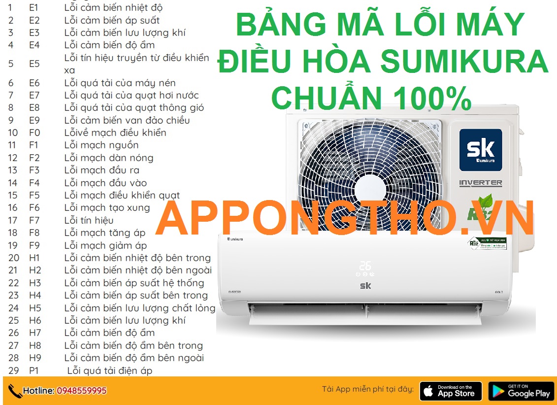
Cách sửa máy điều hòa Sumikura báo lỗi chuẩn an toàn
Mục ChínhCách sửa máy điều hòa Sumikura báo lỗi chuẩn an toànNhận Biết Các Sự Cố và Lỗi Trên Điều Hòa SumikuraHướng Dẫn Kiểm Tra…

Thợ bảo dưỡng điều hòa chỉ 200.000 VNĐ chuẩn quy trình
Mục ChínhThợ bảo dưỡng điều hòa chỉ 200.000 VNĐ chuẩn quy trìnhQuy trình bảo dưỡng điều hòa 200.000 VNĐ1. Kiểm Tra Tổng Quan2. Vệ Sinh…
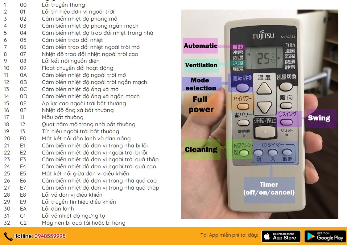
Cách Sửa Full Mã lỗi máy điều hòa Fujitsu Bởi App Ong Thợ
Mục ChínhCách Sửa Full Mã lỗi máy điều hòa Fujitsu Bởi App Ong Thợ1. Hiểu Các Mã Lỗi Điều Hòa Fujitsu2. Cách Sửa Mã Lỗi…

Tự chỉnh điều hòa Mitsubishi báo lỗi cùng chuyên gia
Mục ChínhTự chỉnh điều hòa Mitsubishi báo lỗi cùng chuyên giaBảng Mã Lỗi Điều Hòa Mitsubishi ElectricCách Kiểm Tra Mã LỗiLợi Ích Của Việc Tự…
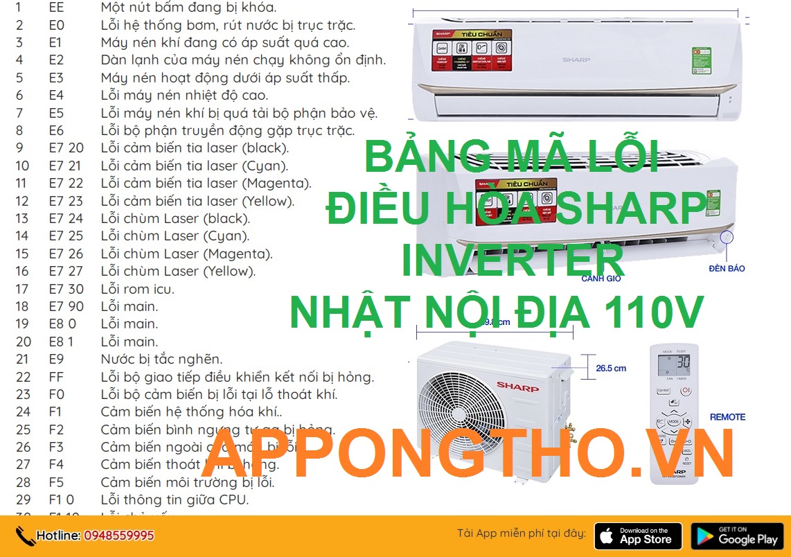
Tự sửa 105 mã lỗi điều hòa Sharp Inverter cùng App Ong Thợ
Mục ChínhTự sửa 105 mã lỗi điều hòa Sharp Inverter cùng App Ong Thợ10 Cách Tự Sửa Lỗi Điều Hòa Sharp sau1. Kiểm tra mã…